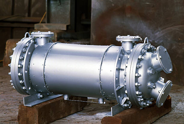
Two coolers can have the same surface area, the same materials and the same price, and still perform very differently. The reason is almost always geometry. How the fluid is routed, how fast it moves, how many times it turns around, how the tubes are arranged. People tend to compare headline numbers, area and duty, and ignore the internal layout, which is a bit like comparing two cars by engine size alone. If you’re weighing a Shell & Tube heat exchanger against an HCF heat exchanger, understanding the internal arrangement tells you far more than the brochure ever will. It also helps you ask better questions and spot datasheets that don’t quite make sense. So let’s open the thing up, metaphorically, and look at what’s actually going on inside.
Why geometry matters more than people think
Here’s the basic trade off behind every shell and tube design. You want the fluids to move fast, because speed boosts heat transfer and keeps surfaces clean. But speed costs pressure drop, which means pumping energy and a limit on what your pumps can deliver. Everything in the internal layout is a negotiation between those two things.
Designers have a handful of levers. How many passes the fluid makes through the tubes. How many passes it makes on the shell side. How the baffles are cut and spaced. How the tubes are arranged and how tightly they’re packed. How long and how wide the tubes are. Each lever shifts velocity, pressure drop, turbulence, fouling tendency and cleaning access.
Change one and the others respond. Add tube passes and tube side velocity rises, but pressure drop rises faster than velocity. Tighten the baffle spacing and shell side heat transfer improves, but so does the resistance and the risk of dead spots.
The result is that there’s rarely a single best design for a given duty. There’s a family of reasonable designs, each balancing the trade offs slightly differently, and the right one depends on your priorities, pumping limits, fouling behaviour and budget. Knowing the levers lets you judge whether a supplier’s choice makes sense.
Tube passes and the speed of the tube side
Let’s start inside the tubes. In a single pass design, fluid enters one end of the bundle, flows straight through all the tubes in parallel, and leaves the other end. Simple, with low pressure drop, but the velocity is limited by the flow divided across all the tubes.
To speed things up, designers add passes. Partition plates in the end headers divide the bundle into sections, forcing the fluid to turn around and flow back through a different group of tubes. With two passes, the same flow goes through half as many tubes at a time, so velocity roughly doubles. With four passes, it quadruples.
Faster flow does good things. Heat transfer on the tube side improves, because turbulence thins the stagnant film against the wall. Deposits get scrubbed away more effectively, so fouling slows. That’s why passes are common on the dirtier side.
But there’s a price. Pressure drop rises roughly with the square of velocity, plus extra losses in each turn. Doubling velocity can nearly quadruple friction losses, and every pass adds more. At some point your pump runs out of head, or erosion becomes a risk. Tube velocities for water are commonly kept within a moderate band, fast enough to resist fouling, slow enough to avoid erosion, with the exact range depending on tube material and fluid.
Passes also affect cleaning. More passes mean more partition plates and sometimes more complicated headers, though the tubes themselves remain straight and easy to access.
Pass arrangements and the temperature cross
Now a subtler point that catches people out. How passes combine with the shell side flow affects how effectively the unit uses its temperature difference.
The ideal arrangement is pure counterflow, where the hot and cold fluids move in opposite directions along the whole length. It makes the most of the available temperature difference, and it can even cool the hot fluid below the outlet temperature of the cold one. A single pass on each side, arranged countercurrently, achieves it.
But multi pass tubes mean that some of the tube side flow runs the same direction as the shell side flow, parallel flow, while some runs against it. The result is less efficient than pure counterflow. Designers account for this with a correction factor, often called the F factor, which multiplies the ideal temperature difference to give the effective one. Values close to one are good. Values dropping toward 0.8 or below mean the unit is wasting temperature difference, and needs extra area to compensate.
The worst case is a temperature cross, where the cold fluid’s outlet ends up hotter than the hot fluid’s outlet. A single shell with multiple tube passes struggles with this, and the F factor can collapse. The usual fix is using more shells in series, or a different arrangement, so the flow pattern gets closer to true counterflow.
When you read a datasheet, look for the F factor, or ask for it. If it’s low, ask why, and whether a different pass arrangement or multiple shells would do better. It’s a quiet source of oversizing.
Baffles, cuts and spacing
Now to the shell side, where the geometry gets more interesting. Without baffles, the shell side fluid would simply run straight along the tubes, with poor mixing and low heat transfer. Baffles are plates that force it to zigzag across the bundle.
The most common type is the segmental baffle, a plate with a section cut away. Fluid flows through the cut, turns, crosses the bundle, and goes through the next cut, repeating along the length. Two choices matter most. The baffle cut, the percentage of the shell diameter removed, commonly around twenty to forty percent. And the baffle spacing, the distance between baffles.
Close spacing speeds up the cross flow, improving heat transfer, but raises pressure drop and increases the risk of dead zones behind the baffles where dirt collects. Wide spacing lowers pressure drop, but lets more fluid bypass and weakens heat transfer. There’s a sensible range, typically somewhere between about a fifth of the shell diameter and the full diameter, and designers tune within it.
Spacing also affects vibration. Long unsupported tube spans can start to vibrate in the cross flow, and the tubes can wear against baffles or each other. High velocity shell side flow raises the risk. Sometimes extra supports or different baffle types are used in sensitive areas.
Other baffle styles exist. Disc and doughnut baffles, rod baffles and helical baffles reduce dead zones, cut vibration, or lower pressure drop for particular duties. They cost more, and they’re worth it in the right place.
Tube layout, pitch and what it does to cleaning
The way tubes are arranged inside the bundle affects performance and, importantly, access.
The two classic layouts are triangular and square. Triangular, often described by an angle of thirty degrees, packs more tubes into a given shell, which means more area and often better heat transfer, because the flow path is more tortuous. But the tubes sit so close together that you can’t get a brush or lance between them from outside, so the shell side can only be cleaned chemically.
Square layouts, ninety degrees, or rotated square at forty five, leave straight lanes between rows of tubes. They pack fewer tubes and give somewhat lower heat transfer, but you can push a cleaning tool down the lanes and mechanically clean the outsides of the tubes, provided the bundle is removable. That’s why dirty shell side fluids often call for square pitch.
Pitch, the centre to centre spacing, matters too. Tighter pitch means more tubes and higher shell side velocity, but narrower gaps that foul and resist cleaning. Typical practice keeps a certain ratio of pitch to tube diameter, leaving enough clearance for cleaning and flow.
Tube arrangement also interacts with baffles and vibration. Together they shape how evenly the shell side fluid flows across the bundle.
When fouling matters, ask which layout is used and why. It tells you immediately whether shell side cleaning is possible.
Tube diameter and length
Two more levers come down to the tubes themselves.
Diameter first. Smaller tubes give more surface area per unit of volume, so the unit can be more compact, and velocities are easier to achieve at moderate flow rates. But they’re harder to clean, because there’s less room for brushes, and they block more easily. Larger tubes are tougher, easier to clean and better for dirty fluids, but you need more of them, or longer ones, to get the same area, and the unit grows.
Common tube outside diameters in industrial work are around nineteen to twenty five millimetres, a compromise between compactness and cleanability. For heavily fouling duties, larger sizes sometimes make sense.
Wall thickness affects pressure rating, corrosion allowance, heat transfer and cost. Thicker walls tolerate more pressure and corrosion, but slightly reduce heat transfer and add weight. Corrosion allowance matters if the fluids are aggressive.
Length is the other variable. For a given area, you can use shorter, fatter bundles or longer, slimmer ones. Long, slender units have higher tube side velocities for the same flow, and are often more economical to build, but need space for pulling the bundle, which equals the tube length plus clearance. Where space is limited, shorter bundles or U tube arrangements may be necessary.
So tube geometry is partly a mechanical and layout question. Ask what clearance you need for bundle removal, and check it exists on site.
Where an HCF heat exchanger fits, and what to ask about its layout
Now to the other unit in your comparison. I’m not going to quote exact ratings or internal details for the HCF heat exchanger. They depend on the version and conditions, and the current datasheet and manual are where those belong. What I can do is tell you which geometry questions to ask.
How many tube passes and shell passes does the arrangement use, and what velocities does that give on each side at your flows? What pressure drop results, and does it fit your pump limits? What’s the F factor, or equivalent measure of how well the flow pattern uses the temperature difference at your duty?
What baffle type, cut and spacing are used, and what shell side velocity and vibration margin does that imply? Is there protection against tube vibration at your highest flow?
What tube layout, diameter and length are used, and does that allow cleaning of both sides in the way your fluids require? Is the bundle removable, and what clearance is needed?
What’s the fouling allowance, and how does it relate to the velocities? And what are the cleaning recommendations for your fluids?
Compare those answers with what a conventional Shell & Tube heat exchanger would give for the same duty. Differences in internal arrangement often explain differences in price, size and maintenance. Neither is automatically better. The right choice is whichever one balances the trade offs best for your fluids, pumping limits and cleaning needs.
Putting the geometry together for a real duty
So how do you use all this without becoming a thermal designer? With a few sanity checks.
First, check the velocities. Tube side velocity should sit in a sensible band, fast enough to resist fouling, not so fast as to erode. Shell side velocity should be moderate, with a margin against vibration. If either looks extreme, ask why.
Second, check the pressure drops. Each side’s pressure drop should fit within what your pumps can supply, with room to spare for fouling, since pressure drop rises as deposits build. A design that uses every last kilopascal on day one has no margin.
Third, look at the F factor. If it’s well below about 0.8, the pass arrangement is wasting temperature difference, and you may be paying for area you don’t need.
Fourth, think about cleaning. Match the layout to your fouling. Dirty tube side fluid wants straight tubes and removable covers. Dirty shell side fluid wants square pitch and a removable bundle. Both clean, and you have more freedom.
Fifth, consider the future. If load or fouling might increase, ask how the design copes. Can passes be changed? Is there space for another shell?
Finally, remember the basics. Record a baseline of temperatures, flows and pressure drops when the unit is new, so you can compare later. Geometry sets what the unit can do. Operating practice decides how long it keeps doing it.
Conclusion
So, how do tube passes and baffles really change cooler performance? They set the balance between heat transfer and pressure drop, control velocities that decide how fast the unit fouls, determine how well the temperature difference is used, and dictate whether you can clean it properly. A Shell & Tube heat exchanger offers many levers, passes, baffle cut and spacing, tube layout, diameter and length, and the right combination depends on your fluids, pumps and maintenance habits. An HCF heat exchanger should be judged the same way, by asking what its internal arrangement does for your duty, not just by comparing area and price.
Check velocities and pressure drops. Look at the F factor. Match the layout to your fouling and cleaning needs. Ask suppliers to explain their choices, and record a baseline once it’s running. Do that and the unit you choose will behave on your plant the way the datasheet promises.
FAQs
What do tube passes do in a shell and tube cooler?
They divide the tube bundle into sections so the fluid flows back and forth, raising velocity and heat transfer and slowing fouling, at the cost of higher pressure drop. More passes mean faster flow but more pumping effort.
What is the F factor on a datasheet?
It’s a correction showing how effectively the flow arrangement uses the available temperature difference compared with pure counterflow. Values near one are good, while low values suggest wasted area and a possible need for a different arrangement or multiple shells.
How do baffles affect performance?
They force shell side fluid across the tubes, improving heat transfer. Closer spacing raises transfer and pressure drop and may create dead zones, while wider spacing lowers resistance but allows bypassing, and long unsupported spans can increase vibration risk.
Why does tube layout matter for cleaning?
Triangular layouts pack more tubes but leave no cleaning lanes, so the shell side can only be chemically cleaned. Square layouts leave straight lanes for mechanical cleaning of the tube exteriors when the bundle is removable.
What should I ask about an HCF heat exchanger layout?
Ask about tube and shell passes, velocities, pressure drops, F factor, baffle type, cut and spacing, vibration margin, tube layout, diameter and length, bundle removability, cleaning recommendations and fouling allowance, using the current datasheet.
How do I sanity check a shell and tube design?
Confirm velocities are in a sensible band, pressure drops fit your pumps with margin, the F factor is reasonable, the layout suits your cleaning needs and the unit fits the space including bundle removal clearance.